Level 3 Project
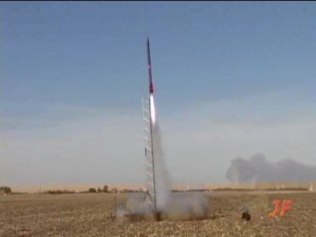
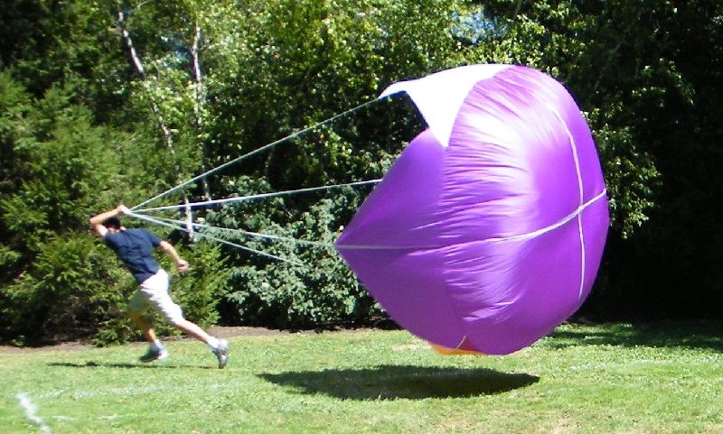
Judy successfully completed her Level 3 cert at Midwest Power 8 in 2010. The Dark Star was renamed the Ultimate Wildflower for the cert flight. It achieved 7000 feet on an M1675 Pink motor.
VIDEO AND PHOTOS BY JUSTIN FARRAND, the official videographer for Midwest Power. Thanks so much to Justin for providing us this footage! The video below was excerpted from the official Midwest Power 8 video. See below for details on how to get your very own copy of the full video. Please be patient with the video player - it takes a few minutes to load and does a nice impersonation of a black hole until it does. Really, there's something there, but you may have to click the play button a few times. (Sorry, the video will not show up on mobile devices.) The inflight photo was cut from the video.


To get the full copy of the Midwest Power 8 video (highly recommended, it is awesome!) contact Justin directly (hprjf AT aol DOT com) to buy via PayPal, or purchase it from Wildman Rocketry. Click here to watch the teaser for the full video. If you like rockets, you'll love this video!
Here's a photo of the test flight (pre-paint) on a CTI L2370 White Thunder. The test flight achieved 6300 feet. Photo by Jackson Lubin (we finally worked the camera right!).

This rest of this page was originally for the purpose of documenting progress on my Level 3 project for my TAPs. Construction photographs taken by Jackson Lubin.
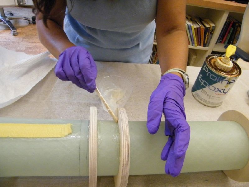
Epoxy used is Pro-line, with silica and chopped carbon fiber fillers.
Table of Contents (Click on area to quickly scroll to that section on this page).
1) Project Description
2) Construction of the Motor Tube and Centering Ring Assembly
3) Lower Fin Attachment
4) Upper Fin Attachment
5) Fin Fillets
6) Miscellaneous Construction
7) Av Bay and Recovery Electronics
8) Back-up Motor Plan
9) Launch Day Checklist
Project Description
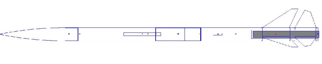
RockSim drawing and basic details:
Length: 143.6254 In. , Diameter: 6.0000 In. , Span diameter: 23.0000 In.
Mass 695.8402 Oz. , Selected stage mass 695.8402 Oz.
CG: 98.5323 In., CP: 124.5970 In., Margin: 4.34 Overstable
Engines: [M1675-PK-None, ]
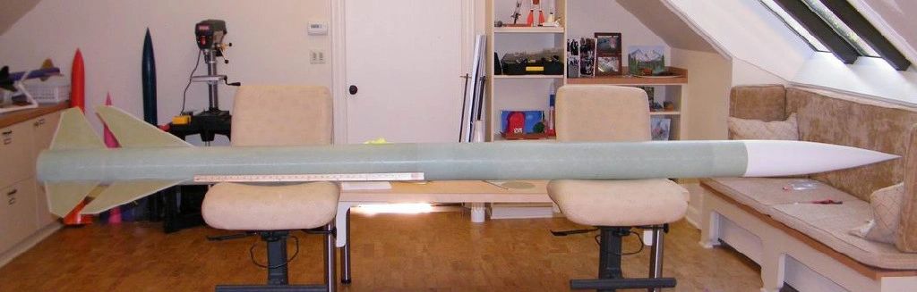
Parts and Design Overview (yardstick and 12 inch ruler for scale):
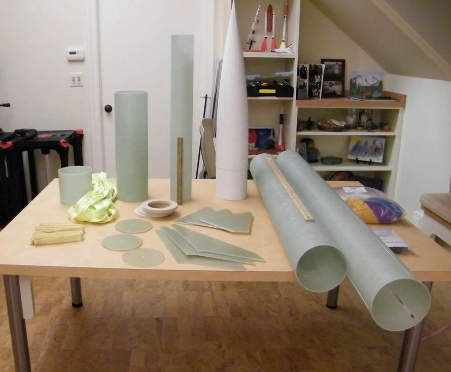
Ultimate Dark Star parts listing
Kit parts:
Fiberglass booster, pre slotted - 6 inch diameter, 60 inches long
Fiberglass payload - 6 inch diameter, 48 inches long
Fiberglass coupler/altimeter bay with switch band - total length 20 inches
Fiberglass motor mount tube - 98 mm, 30 inches long
Fiberglass nose cone 5-1
3 – 0.187 inch thick Fiberglass fin sets (upper and lower)
5 - Fiberglass bulk plates (1-NC, 2-coupler and 2-airframe)
4 - Wood centering rings, ½ inch thick
3 - Welded eye bolts
Kevlar shock cord harness
Additional construction parts:
Aeropac motor retainer
Aeropac 98 to 75 motor adapter
Pro Line Epoxy with silica and chopped carbon fiber fillers
Rail buttons
Quicklinks
Plastic rivets
Recovery:
Main parachute: Skyangle Cert 3 XXL
Drogue parachute: Skyangle Cert 3 drogue
1 inch Nylon shock cord, 25 feet total
Shock cord protector
Fire blankets, drogue and main
Avionics:
Rdas tiny altimeter
PerfectFlite HiAlt45K altimeter (backup)
TLA GPS tracker or Rocket Tracker radio tracker
5/16 threaded rod
Plywood sled
PVC ejection charge holders
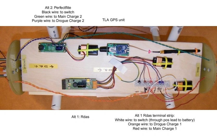
Terminal strips for drogue and main e-matches; Rdas loom At apogee - drogue parachute: Skyangle Cert 3 drogue At 1000 feet - main parachute: Skyangle Cert 3 XXL diagram of recovery electronics:
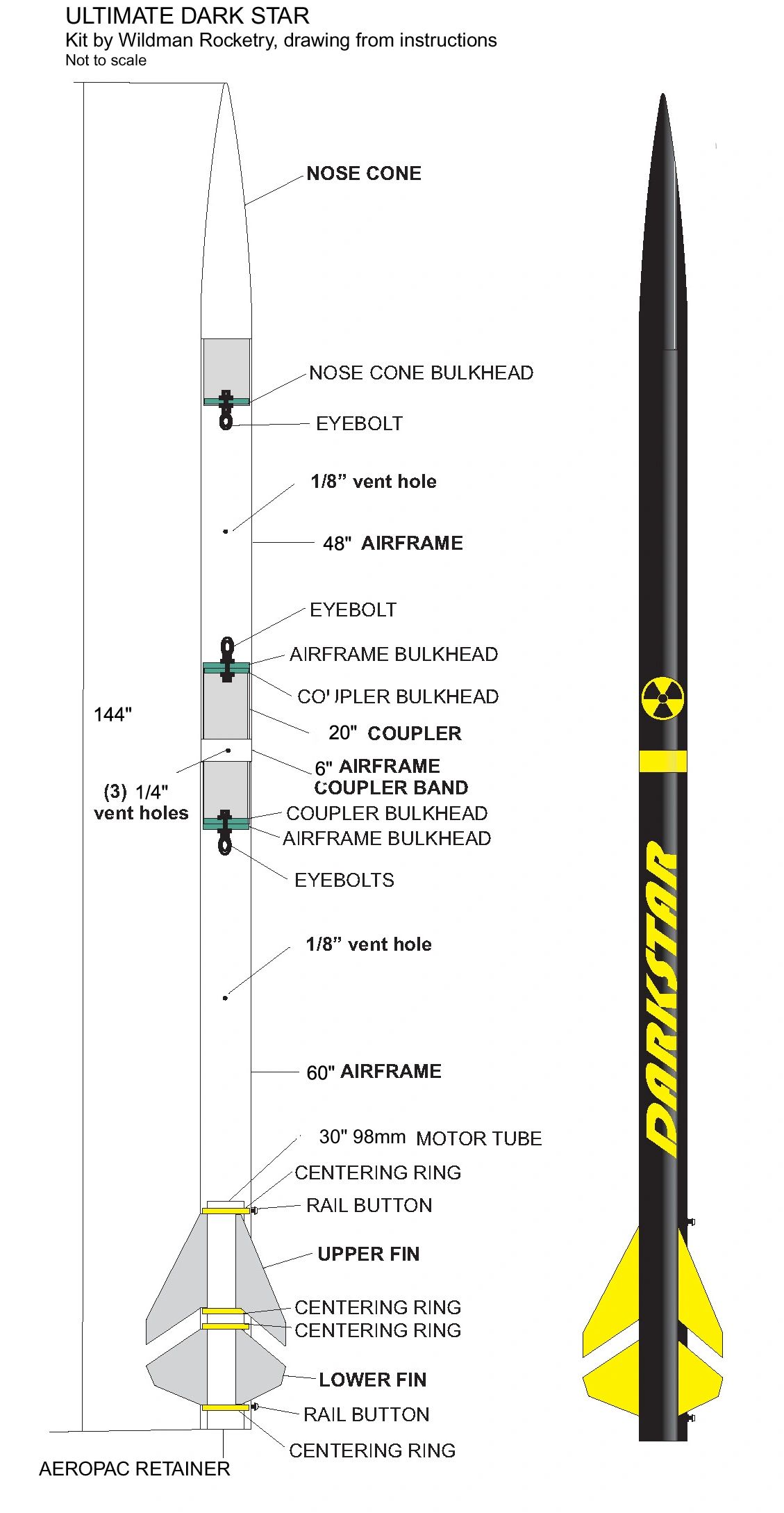
Assembly Diagram (not to scale):
Dry Fit: (yard stick for scale)
Motor Thrust curve and information can be found by clicking on the motor name here:
CTI M1675 Pink
Construction of the Motor Tube and Centering Ring Assembly
First step in construction was to sand all areas that will be epoxied with 60 grit sandpaper, and all areas that will get painted with 220 grit.
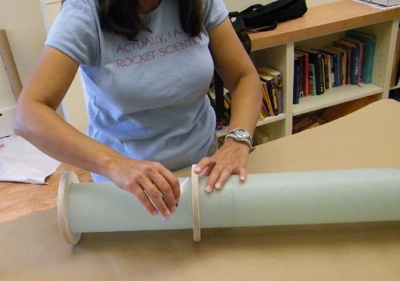
My approach to the motor tube construction is marked by frequent measuring and dry fitting. With the design of the Dark Star and the use of internal injected fillets, it is important that the centering rings are mounted so that the fins will fit tight. The tightness of the parts ensures that epoxy stays where it is injected in order to properly adhere inner parts, and to ensure that weight of epoxy is evenly distributed. To place centering rings, I began by measuring and marking onto the motor tube the distance from the end of the body tube to the fin slots. Dry fit of fins is used to determine exact positions.

Tack with CA glue before another dry fit to ensure fins fit tight.
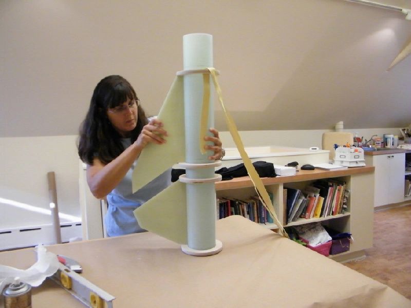
Make sure fins are level so that they will center properly. Repeat process for top two centering rings, then dry fit fins to ensure that tacked fins were placed properly.


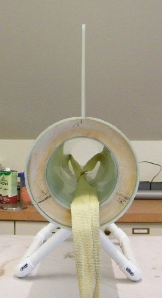
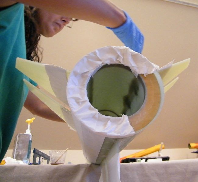
Now, attach shock cord, making sure not to get ANY epoxy on the shock cord above the centering ring where it is attached.

No epoxy on the unattached part of the shock cord!
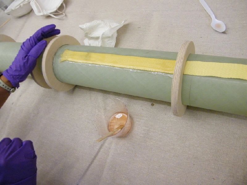
For extra strength of shock cord attachment, another encapsulation coat of epoxy, this time with chopped carbon fiber, just to thicken the mix so that it encapsulates better. Still no epoxy on the unattached part of the shock cord.

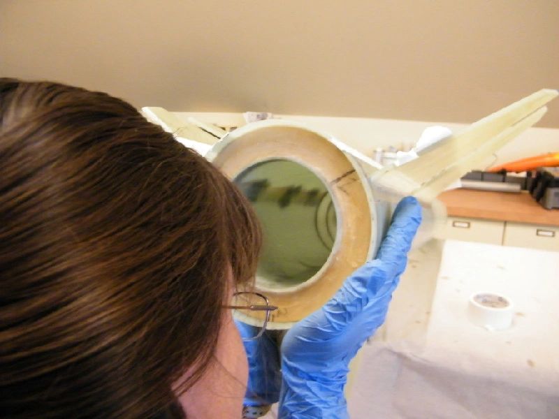
The centering rings have a very loose fit around the motor tube. To increase attachment, and prevent mess during injected fillets, I put a small fillet of thickened epoxy (thickened with silica) around the centering ring where it attaches to the motor tube, only on the side of the centering rings that will not touch the fins (the area of the motor tube where the fins attach must be clean to ensure a tight fit). After it set, I epoxied the centering ring to the motor tube, making sure to keep the area that will touch the fins clean. Additional epoxy will enhance attachment during injected fillets.
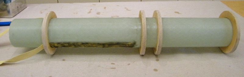
Finished motor tube assembly:
Dry fit of fins with motor tube assembly:
Lower Fin Attachment
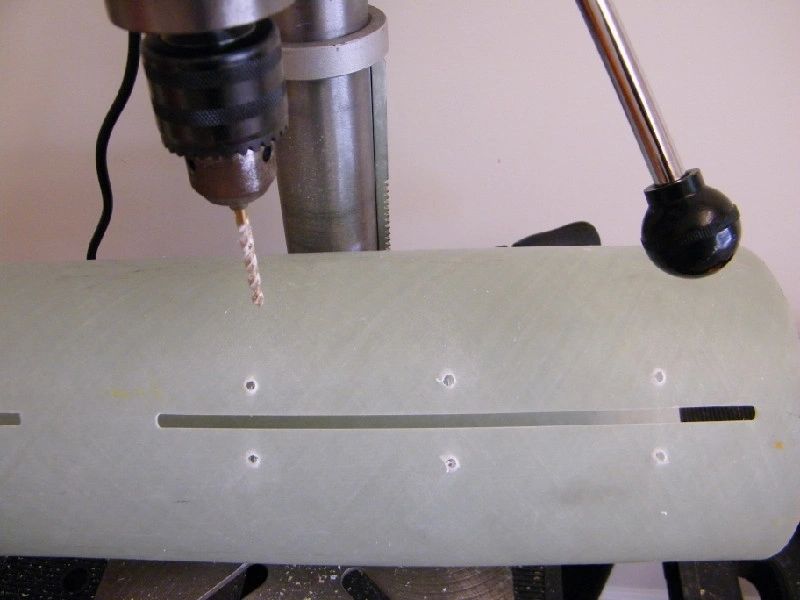
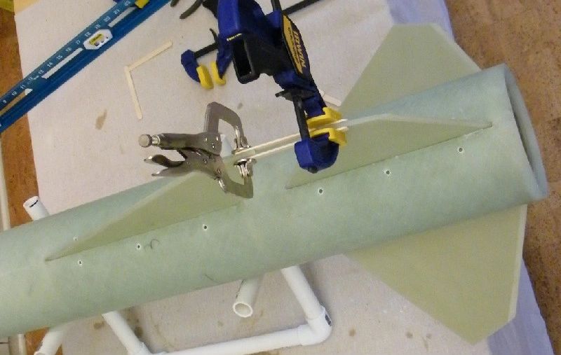
Before attaching fins, I drilled 3 holes on each side of every fin slot, in preparation for the injected fin fillets.
I kept up the emphasis on measuring and dry fitting while tacking on the lower fins. The fins need to sit exactly perpendicular to the motor tube, and fit tightly against both centering rings in order to ensure that the epoxy from the internal fillets stays where it is supposed to. The motor mount is attached at the same time as the fins are attached, so my first step was to insert the motor tube and dry fit all the fins to ensure motor tube is properly placed.

Using a new tip form the most recent version of Wildman's instructions (thanks, Jim - good idea!), I dry fitted each fin, and then drew a line where the perfectly abutted fin touches the fin slot. This helps me to know whether or not the fin is fully inserted when I tack.

I tacked fins with epoxy thickened with silica.

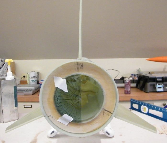
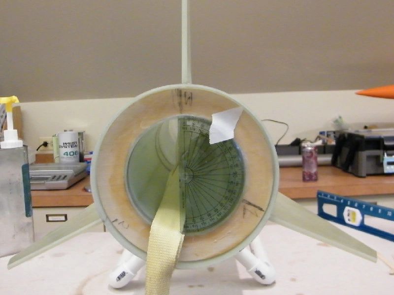
I found that working with a 98mm motor mount has an unexpected benefit. Every home with grade school kids has the standard issue 10 cm protractor. This handy little device is the perfect tool to ensure that fins extending off a 98mm motor tube are placed exactly evenly apart, and extend at the proper angle.
Upper Fin Attachment
I attached the upper in the same way that I attached the lower fins, by tacking with silica thickened epoxy. I ensured that each fin was properly abutted by drawing a line on each fin that shows where the properly inserted fin would meet the fin slot.


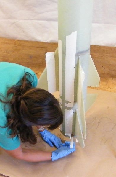
To make sure that each upper fin was exactly aligned with the corresponding lower fin (which were all set at the proper angles), I used straight sticks on both sides of each fin to gain the proper alignment, and clamped them in place to dry.


After tacking all three fins and ensuring that they were straight, I moved onto internal fin fillets.
Fin Fillets
Before injecting fillets, I noticed that the centering rings were a bit more loose than I would have liked them to be. The motor tube assembly required a firm push to get it into the body tube, but the rings were still slightly more loose than in other projects of this design that I have worked on. So, I added some extra epoxy to ensure proper attachment. The instructions specified an injected or poured fillet on top of the top centering ring, done after the internal fillets. However, I moved this step up in order to keep epoxy from leaking onto the shock cord (which I protected from epoxy in previous steps). Before injecting fin fillets, I injected epoxy mixed with chopped carbon fiber into a hole drilled just above the top centering ring. Epoxy did leak down somewhat from the pour over the top centering ring, showing that I was correct to pour the fillet first.

After this was dry, I injected epoxy with chopped carbon fiber into the fin cavity above each centering ring and gently rolled the tube around to spread the epoxy. This was to ensure that all centering rings are strongly attached to the body tube.
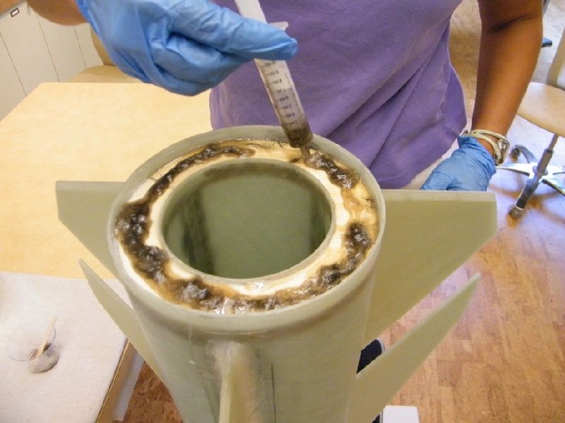
When this was dry, I began on the injected internal fillets. With one fin straight down, I did two sets of fillets at one time. I used one-half syringe (5ml) of epoxy mixed with chopped carbon fiber in each hole.

After injecting each fillet, I moved the body tube up and down to ensure even spreading.
I had no epoxy leaking between the fins, which means that each fin is tight and perpendicular to the motor tube.
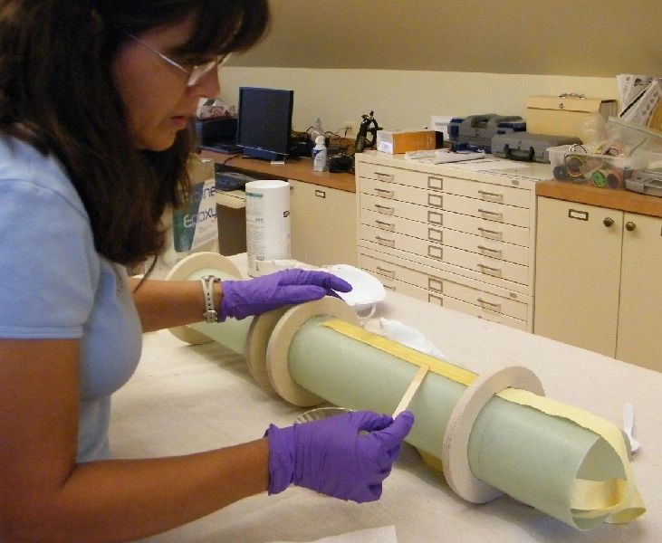
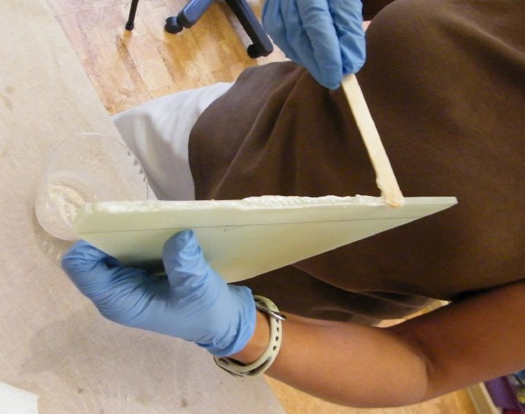
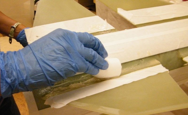
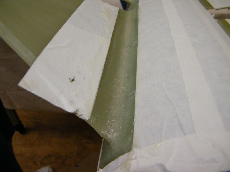
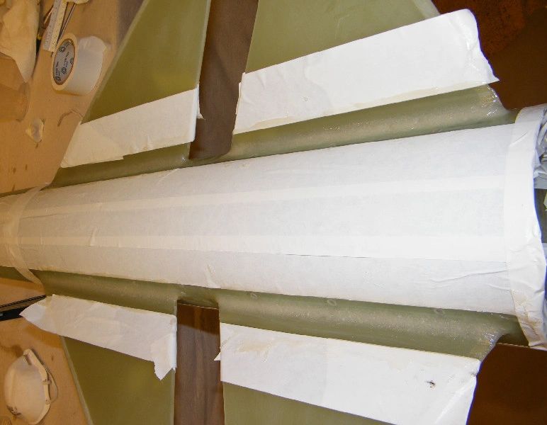
I did the internal and the external fillets at approximately the same time. After each set of internal fillets, I made the externals. Before beginning the whole process, I had taped external fillet guides on the side of each fin. This was to make sanding of the external fillets easier. The tape was set at the point where my "fillet tool" (a 1 inch PVC elbow) contacted the body tube, on one side, and the fin, on the other. For the fillets, I used epoxy thickened with silica. I smoothed each fillet with the PVC elbow, to minimize later sanding. The external fillet process closed up all of the holes that were used for injecting fillets. During this time, I also sealed the hole used for the poured fillet on the top centering ring, thus ensuring that all body tube holes (except the vent hole) are sealed.
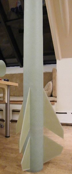
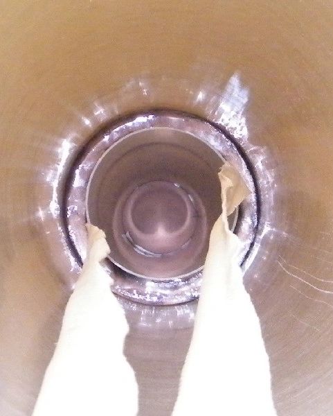
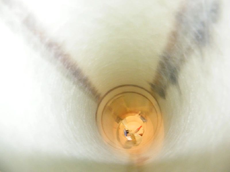
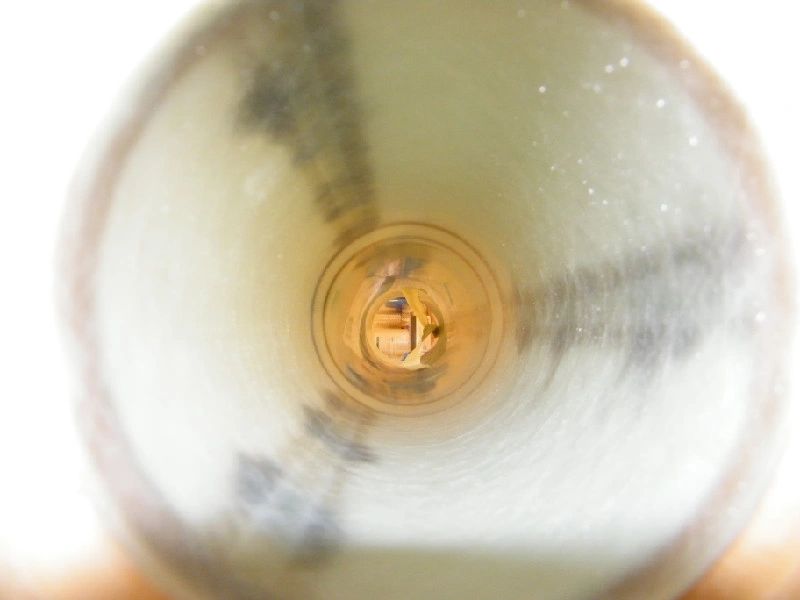
Inside view after three sets of internal and external fillets:
After these were dry, the final step in the fin can assembly was to pour epoxy on the bottom centering ring. Although I had met the purpose of this fillet - to increase attachment of the bottom centering ring to the body tube - by injecting epoxy from above in a previous step, this step still needed to be done, because I had accounted for it when mounting the centering rings. The motor tube would not be flush with the centering ring, as required for the retainer installation, without it. I was careful not to spill any epoxy into the motor tube.
Miscellaneous Construction
While epoxy was drying for the above steps, I also completed the following miscellaneous steps:
Attach av bay switch band:
Epoxy av bay outer bulk plates to av bay inner bulk plates, to provide better seal on the av bay (items on top are for the purpose of weighting plates until dry):
Attach bulk plate to nose cone with epoxy/chopped carbon fiber mix:

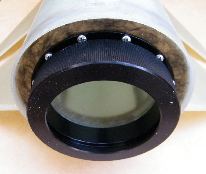
Attach AeroPac motor retainer:
Because the below listed steps are visible from the outside of the rocket, I have not included pictures.
shear pin holes (3 each on nose cone shoulder/body tube)
plastic rivet holes (3 each to keep av bay attached to main body tube section)
vent holes (3/16th inch holes each in drogue and main sections)
static port holes (3 holes, 1/4 inch each, away from plastic rivets and other air flow disturbances)
Av Bay and Recovery Electronics
Summary of Recovery plan:

Wired av bay, labeled:
Charge amounts:
Charges give 12 psi (info central's calculator):
6 grams for main
5.5 grams for drogue
Charges were ground tested successfully on Sept 18

Back-up Motor Plan
If there are substantial winds on launch day, the M1675 may not be fast enough to deliver a stable launch. If it is windy, I will launch on a CTI M3700 White Thunder (75mm 6-grain, 6800 Ns total impulse). The burn time for the M3700 is almost 2 seconds shorter (1.8 seconds, versus 3.7 for the M1675), despite being slightly larger (6800 total newtons, versus 6162 for the M1675). The thrust curve for this motor can be found here: M3700.
Data for the rocket loaded with the M3700:
Weight: 47 pounds
Thrust to weight: 17.1 : 1 (over double the ratio with the M1675)
Center of pressure: 124 inches from nose (same)
Center of gravity: 101 inches from nose
Max velocity: 1014 ft/sec
Max altitude: 9400 feet
Launch Day Checklist
Click here to view launch day checklist: checklist
